Put a motion sensor and a wall switch in the same room without configuring them for each other, and they get in each other’s way. The sensor switches off a light someone turned on by hand. The button needs two presses, because it does not know the sensor has already switched the light on.
The fix is one button command that drives two things at once: the light and the sensor’s block input.
- Switched on at the button — the light stays on and the sensor is paused, so it will not turn the light off.
- Switched off at the button — the light goes off and the sensor takes over again.
- The button knows the luminaire status — it always knows whether the light is on and switches it off with the first press.
Below is how it works and how to set it up in ETS, using an Elsner Intra-Sewi KNX TH-L-Pr sensor and a Basalte Sentido KNX button as the example. First the basic pairing: one sensor, one button, one LED strip. Then what can be added on top.
What the resident experiences
A motion sensor reacts to moving heat, not to a person as such. Someone standing or sitting still is, as far as the sensor knows, an empty room. That is why the sensor has a switch-off delay and the resident has a manual mode at the button.
- 1Walk in — the light comes on by itself.
- 2Walk out — the light goes off once the sensor has seen no motion for the length of the delay.
- 3Want the light to stay on no matter what — switch it on at the button. It stays on until you switch it off.
- 4Switch it off at the button — the light goes off and the sensor watches the room again.
- 5The sensor switched the light on and you press the button — the light goes off with the first press. A second press switches it on in manual mode.
Three group addresses
For a switch and a motion sensor to work as a pair, three group addresses are all it takes. The example is LED strip L30 on a dimmer, sensor PIR3 and the button by the door.
- 11/0/32 “L30 On/Off” — switches the lighting group, here the LED strip. Linked to the dimmer channel the strip is wired to and to the motion sensor’s output.
- 21/5/4 “L30 On/Off Pir3” — switches the strip from the button. Linked to the button that controls the light, to the sensor’s block object and to the same dimmer channel.
- 31/1/32 “L30 On/Off St” — status of the dimmer channel. It tells the button what state the strip is in and what to send on the next press. Linked to the dimmer’s status object and, as the second address, to the button.
Setting up the Elsner Intra-Sewi sensor in ETS
The sensor runs in Master mode: it decides on its own whether there is motion and sends 1 or 0 to the light. The button’s command arrives at a separate block input. Parameter names are given as they appear in ETS.
Motion detector page
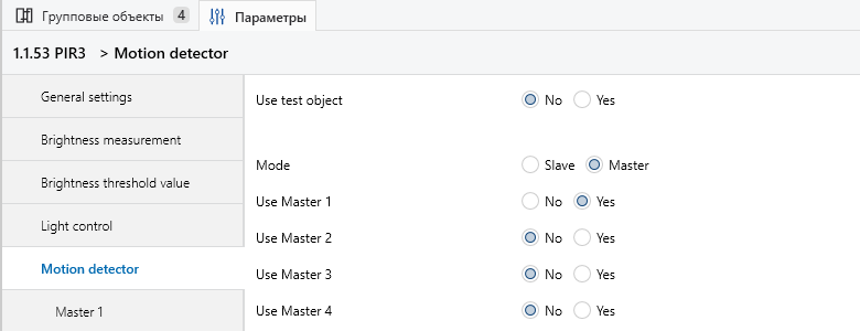
| Parameter | Value | Why |
|---|---|---|
| Mode | Master | The sensor controls the light itself. In Slave mode it only passes motion on to another sensor |
| Use Master 1 | Yes | One output for one lighting zone. Master 2–4 are for a sensor that drives several zones |
| Use test object | No | Not used in operation |
Master 1 page
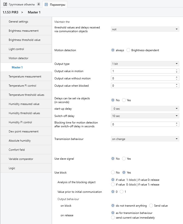
| Parameter | Value | Why |
|---|---|---|
| Motion detection | always | The sensor reacts day and night. Brightness-dependent reacts only below a lux threshold |
| Output type | 1 bit | Plain on and off |
| Output value in motion / without motion | 1 / 0 | Motion — light on; no motion — light off |
| Output value when blocked | 0 | Only used if Send value is selected for “on block”. Not used here |
| Delays can be set via objects | No | Delays are set in ETS and cannot be changed from the bus |
| start-up delay | 0 sec | The light comes on as soon as there is motion |
| Switch-off delay | 10 sec | Tuned by testing on site — see the section on the delay |
| Blocking time for motion detection after switch-off delay | 0 | A pause in which the sensor ignores motion after the light goes off. Not needed here: the switch is outside the sensor’s coverage |
| Transmission behaviour | on change | A telegram goes out only when the state changes, no extra traffic |
| Use slave signal | No | No extension sensors in this zone |
| Use block | Yes | Enables the block input, where the button’s command arrives |
| Analysis of the blocking object | 1: block, 0: release | Matches the button: switched on — blocked, switched off — released |
| Value prior to initial communication | 0 | After a power cut the sensor starts unblocked, in automatic mode |
| on block | do not transmit anything | The light stays the way the button left it |
| on release | as for transmission behaviour | The sensor sends nothing at the moment it is released, only at its next state change |
Sensor objects

| Object | Linked to |
|---|---|
| 36 Master 1: Output | 1/0/32 “L30 On/Off” — light from the sensor |
| 41 Master 1: Block (1 = Blocking) | 1/5/4 “L30 On/Off Pir3” — the command from the button. The other addresses in the screenshot are “All off” and shared buttons, covered below |
| 42 Master 1: Central Off | Not used |
Setting up the Basalte Sentido button in ETS
The button is configured as a dimmer: a short press switches the light, a long press changes the brightness. What matters is that the switching object is linked to two addresses.
General page
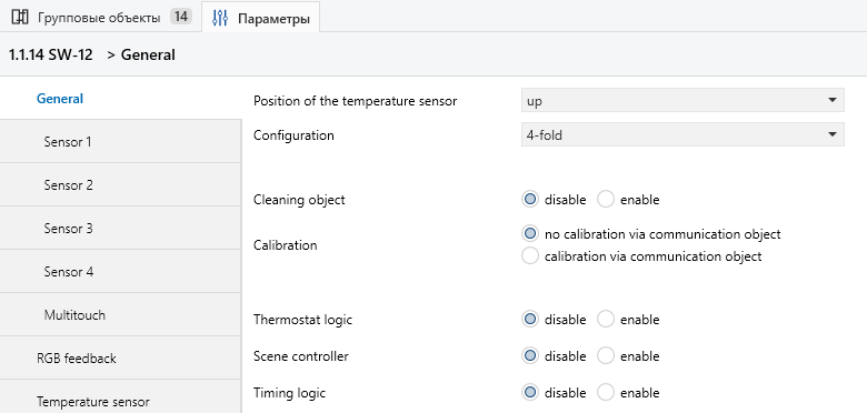
| Parameter | Value | Why |
|---|---|---|
| Configuration | 4-fold | Four independent buttons |
| Thermostat logic, Scene controller, Timing logic | disable | Not needed for this scheme |
Button page (Sensor 2)
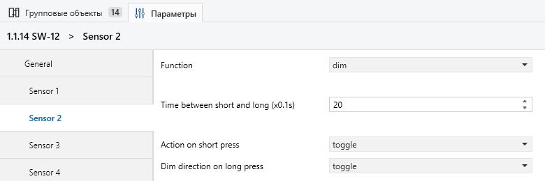
| Parameter | Value | Why |
|---|---|---|
| Function | dim | Short press switches on and off, long press dims |
| Time between short and long (x0.1s) | 20 | A press longer than 2 seconds counts as long |
| Action on short press | toggle | Each press flips the state |
| Dim direction on long press | toggle | Long presses alternate between brighter and darker |
Button objects

| Object | Address | Role of the address |
|---|---|---|
| 19 sensor 2 – switch | 1/5/4 “L30 On/Off Pir3” | Sends: light + sensor block |
| 1/1/32 “L30 On/Off St” | Listens: the actual state of the strip | |
| 20 sensor 2 – dim | 1/2/32 | Dimming |
In ETS an object sends only to the first address in its list; it just listens to the rest. That is why the status sits second. When the sensor switches the light on, the dimmer sends status 1, the button stores it, and its next press sends 0. For this the button object needs the W (write) flag, and the dimmer’s status object needs the T (transmit) flag.
What happens on the bus
Every action of the resident is one telegram to one address. The table doubles as a test plan on site, with the ETS group monitor open.
| Situation | Telegram on the bus | Result |
|---|---|---|
| Someone walks in | Sensor: 1 to “L30 On/Off” | Light on |
| Someone walks out | Sensor: 0 to “L30 On/Off” after the delay | Light off |
| Light off, button pressed | Button: 1 to “L30 On/Off Pir3” | Light on, sensor blocked and silent |
| Light on from the button, pressed again | Button: 0 to “L30 On/Off Pir3” | Light off, block released, the sensor is in charge again |
| Sensor switched the light on, button pressed | The button already has status 1 from “L30 On/Off St” and sends 0 | Light off with the first press |
| Power cut and back | — | The sensor starts unblocked: Value prior to initial communication = 0 |
Switch-off delay and switch position
There is no universal switch-off delay. It depends on the sensor type, where it is mounted, its coverage and the sensitivity it is set to, so it is tuned on site.
How to tune the delay
- 1Set the sensor to its working sensitivity.
- 2Behave in the room the way the residents will: walk through, stand, sit still.
- 3Watch the ETS group monitor for the moment the sensor sends 0.
- 4Adjust the delay until the light stops going off during normal use.
Where the switch goes
In this example the switch is outside the sensor’s coverage. People press the button where the sensor cannot see them, so the pause after switch-off (Blocking time for motion detection after switch-off delay) is not needed.
With the switch inside the coverage, the sensor sees the movement and switches the light back on after the block is released — in that case the pause has to be set.
What can be added
The basic pairing covers one zone. Shared commands are added on top — and each of them must also drive the sensors’ block inputs, or a sensor stays blocked.
One button for several zones
In the master bathroom the toilet is separated from the washbasin area by a wall. So there are two sensors, each driving its own strip with the same three-address scheme.
The shared button by the door sends to 1/0/39 “L30–33 On/Off Pir3-4”. That address is linked to every strip channel and to the block objects of both sensors. On — both zones light up and both sensors pause. Off — everything goes dark and the sensors are back in automatic mode.
“All off”
The “All off” button by the front door sends 0 to 1/0/0 “All Off”. That address is linked not only to every luminaire but also to the block objects of every sensor. Leave home, and every sensor returns to automatic mode, even where a light was switched on by hand.
Keeping the addresses tidy
The “light + block” addresses sit together in their own middle group, 1/5 “PIR”. Anyone servicing the system later can see at a glance which buttons block which sensors.
Common mistakes
Almost every “the sensor has a mind of its own” complaint comes down to one of these settings.
| Mistake | What the resident sees | Fix |
|---|---|---|
| Button and sensor both drive the light, no block | Switched the light on by hand — it goes off on its own after the delay | The button’s command goes both to the light and to the sensor’s block input |
| The button object has no status address | The sensor switched the light on — it takes two presses to switch it off | Add the status as the object’s second address |
| The status address is first in the object’s list | The button does not control the light | Command address first, status second |
| on block: Send value with Output value when blocked = 0 | Pressed “on” — the light flickers and goes off | on block: do not transmit anything |
| Block polarity reversed (0: block) | Switched on by hand — the sensor still turns it off; switched off — the sensor stops working | Analysis of the blocking object: 1 — block, 0 — release |
| “All off” does not release the block | After leaving home, the sensor in a room stays disabled | Link “All Off” to the block input of every sensor |
| Value prior to initial communication = 1 | After a power cut the sensors do nothing until someone presses a button | Keep it at 0 |
| Switch inside the sensor’s coverage and on release: send current value immediately | Switched the light off — it comes straight back on | Place the switch outside the coverage and keep on release: as for transmission behaviour |
Commissioning checklist
- Sensor: Mode = Master, Use Master 1 = Yes
- “L30 On/Off” linked to the sensor output and to the dimmer channel
- “L30 On/Off Pir3” linked to the button, to the sensor’s block input and to the dimmer channel
- “L30 On/Off St” linked to the dimmer status and, as the second address, to the button
- The dimmer’s status object transmits (T flag)
- Use block = Yes, 1 — block, 0 — release
- on block: do not transmit anything; on release: as for transmission behaviour
- Value prior to initial communication = 0
- Switch-off delay tuned by testing in the room
- Every scenario in “What happens on the bus” checked in the group monitor
- Shared buttons and “All off”, if any, are linked to the sensors’ block inputs
- Power switched off and on again: the sensors are back in automatic mode
When this scheme is not enough
The scheme is meant for rooms people pass through briefly: a wardrobe, a bathroom, accent lighting. Elsewhere it needs additions.
- Switch inside the sensor’s coverage — set the pause after switch-off, or move the button.
- Light only when it is dark — Motion detection: Brightness-dependent plus a lux threshold.
- Two sensors covering one zone — a main sensor in Master mode and an extension in Slave mode, with Use slave signal = Yes on the main one.
- Different behaviour by day and by night (night lighting, time-based scenes) — a job for a logic module, not for sensor parameters.